Re-housing a Gl.inet Beryl AX router

A while back I made a dedicated mounting option for use on set for the
Gl.iNet Beryl and Slate
travel routers and
wrote about the benefits of having a dedicated router on set. Since then, it's inspired a others to make clones. While the design I
came up with is great for most users I was looking for a way to make it work
better for my needs. I'd seen others re-house other travel routers in the
past and Rencher Industries has had a
re-housed Gl.iNet
for years. Well, I finally found a bit of time to dedicate to my own project
and tore open the router.
Once inside I was surprised to see not
just the two moveable antenna but a 3rd integrated into the case. Other than
that it's very straight forward with 4 screws holding the PCBA to the
housing.

Here's the layout of the board inside

After I saw what I was dealing with I jumped into CAD and came up with my solution.

The main goals were:
- Maintain access the I/O.
- No external power cabling.
- Integrated 1/4-20 mount.
- Maintain airflow.
- Keep it simple.
It was very important to me that it be powered directly via the USB-C port
with minimal soldering. (I had destroyed routers in the past attempting
power them in different ways due to my poor soldering skills.) I wanted no
outside power cabling so I could just attach a battery, it would start-up
and go. I chose to go with a v-mount option for simplicity but the same
could have been done with an NP-F battery.
One thing to note, is
the way I got power the router board isn't ideal but it is the easiest
solution I could find that didn't risk damaging the router while attempting
to solder a new power input.
Parts used:
- Gl.iNet GL-MT300 (Beryl AX)
- 3D printed housing body & lid (files available HERE)
- 2x m3x8 stainless button head screws
- 4x m3x8 socket head screws
- 2x m3x10 socket head screws
- 8x m3 brass heat set inserts
- 1x 1/4-20 brass heat set insert
- 3x dual band antenna
- 3x SMA bulkhead fittings with IPEX 1 connectors (8inch long)
- 1x mini v-mount battery plate
- 1x USB-C PD PCB
- 1x slim USB cable
- kapton tape
Disclaimer: If you attempt this project you do so at your
own risk. I take no responsibility for any damage to hardware, injury to
yourself or anyone else associated with this modification.
The two printed parts take about 2.5hr to print in
PETG-CF on a Bambu X1C. PETG-CF
is more than capable material for the job. If you don't have a printer try a
service like
CraftCloud to have prints made. (use referral code REFG5NAV0O7)
Assembly is straightforward. However, squeezing everything into place
can take a little persuasion at some points, just be patient.
- Install the heat set inserts into the housing.
- Trim a few inches off the red/black wires on the mini v-mount plate and solder them to the +(red) and -(black) on the USB-C PD board.
- Trim off the nubs from the transformer on the bottom of the USB-C PD board.
- Wrap the back of the USB-C PD board and solder connections with kapton tape.
- Attach the USB cable to the router board.
- Attach the SMA-IPEX cables to the router board.
- Insert the router into the housing and feed the USB cable under the board out the opening in the housing. Attach with 2x m5x10 screws.
- Insert the SMA fittings into the 3 holes. (placement isn't important, can be a bit tricky to align everything I've added a bit more clearance in the final files)
- Put the lid on and attach with the 2x M3x8 stainless button head screws.
- Connect the USB-C cable to the USB-C PD board.
- Neatly place USB-C PD board and the wires in the open area in the housing behind the v-mount battery plate, be sure none are pinched. Attach to the housing with 4x m3x8 socket head screws.
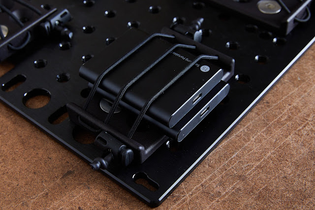
Now you're done. Slap a battery on there. Attach your favorite quick release or a stand mount and you're ready to rock.


I also added a few finishing touches to the housing with my laser to make sure I don't forget what each port does or the management IP address.


|
| The finished product with a detachable stand mount. |
In closing, I have to make a few things clear:
- I will not modify or print the files for anyone.
- I will not make another version for any other router.
- I will not provide any support or answer technical questions regarding this project.