
Electricity, not so shocking: Part 1 of 2
 |
| PIRE wheel with international unit symbols. |
Disclaimer: Everything below pertains to electrical system in North America and specifically the United States with single phase 110-120VAC. Other countries vary. I'm not a licensed electrician, but have many years of experience working first hand with basic electrical wiring on and off set. I've spent the time learning the details, proper safety required and am aware of the risks involved. Carelessness with electricity can result in serious injury or death.
Ohm's Law:
One of the first bits of knowledge anyone working with anything electrical should know is Ohm's law. Which can be simplified as Volts x Amps = Watts. Remember this.You might look at that PIRE wheel above and feel a bit intimidated. But don't be. It's quite simple once you know the variables you're dealing with. So what are those variables?Watts, Amps and Volts are the three variables you should be aware of and I'm sure you've heard of these. Provided you know two of them you can use the wheel to determine the third.
- Watts = Power
- Amps = Amperage or current
- Volts = Electric potential or electromotive force
- Ohms = Resistance
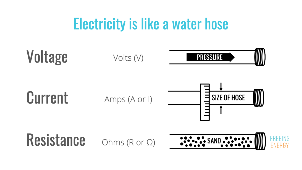 |
| Source: FreeingEnergy.com |
Volts are often seen as the scary number but in reality, knowing the amps that come along with those volts determines the pucker factor. 1000V at 10mA (milliamp) isn't scary but 120V at 20A is.
Now that you know the basic terms, how do you apply that?
Once again, you should know this universal fact:
Volts x Amps = Watts
- 120V x 4A = 480Watts
- 120V x 15A = 1800Watts
- 120V x 20A = 2400Watts
- 1200W/120V= 10A
- 960W/8A= 120V
With the equation you can reverse or rearrange it in any way and it will always be true. To help with this there's PIRE wheel apps for iOS and Android
In the US you will typically be dealing with a 110-120V. (Unless you're in a commercial or industrial setting where 220V+ and 3phase starts to be common.) You can look at the information listed on a device and it typically gives you two values Amps & Volts (sometimes Watts are included). As mentioned before, knowing any two allows you determine the third and since we're focused on 120V that is a constant, known variable.
Keep in mind that Amps listed on a device's power rating plate are for the max load. Amperage isn't always a constant and will vary depending on the load of the device. For example a fan motor might state 12A but that's it's MAX. If it's at a low speed setting it could be much lower, like 3A. Sometimes Amps are listed as a range like 3A-7A. When calculating always use the high end of the range.
There is one more variable you might see and that is frequency which for the US/ North America will be 60hz but that's not anything we need to be concerned with so you can ignore that in this case.
Wire Gauge:
Wire gauge or American Wire Gauge (AWG) is an important factor you should know about. Essentially, the smaller the number, the larger the diameter of the wire and the higher amperage it can handle. Thicker or lower gauge wire offers lower resistance for the current and therefore less heat generated. Think about a tungsten light bulb, the filament is a thin, high resistance wire. By resisting the the current it generates heat and light. This is done in a very controlled matter but you can see how this could be an issue if not controlled.
For stingers/extension cords on a professional level like you encounter on set are almost exclusively #12AWG which offers the lowest resistance in a manageable size and able to support 20A up to 50ft. Stingers/extension cords can be found in #14 and #16 gauge. These aren't inherently bad, they are for lower amperage usage and should be avoided for use with higher amperage applications.
As mentioned before, wire gauge is important because it affects the resistance and heat generated which are crucial to safety. Wire gauge also determines the max length of cable for an application as that resistance over the length can lead to voltage drop and not allow a device to function properly. Longer runs require thicker wire/lower gauge so there isn't a significant voltage or current drop over the run. There are various tables, charts and calculators online to help you determine the wire gauges needs for an application. Here is one.
The wire used in homes is called NM (non-metallic) cable or Romex, it is color coded. These colors can help guide/inform you if you're in a place you can see exposed NM wire or replacing a receptacle.
- White = #14/15A
- Yellow = #12/20A
- Orange = #10/30A
- Grey (UF) = Underground Feeder for running underground, available in various gauges.
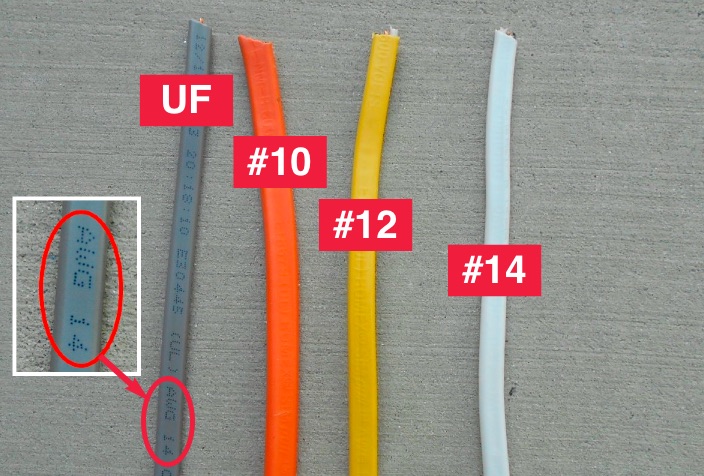 |
| Source: How to Look At a House |
In these cables will be 3 wires or conductors; bare copper (ground), one in black insulation (Hot) and one in white insulation(Neutral). The same is true for a standard stinger/extension cable but the ground will be sheathed in green. (like the image below)
- White = Neutral (It provides the return path for the current provided by the hot wire. The neutral wire is connected to an earth ground.)
- Black = Hot (120V)
- Green = Ground (Like the neutral wire, the ground wire is also connected to an earth ground. However, the neutral and ground wires serve two distinct purposes. The neutral wire forms a part of the live circuit along with the hot wire. In contrast, the ground wire is connected to any metal parts in an appliance, such as a microwave oven or coffee pot. This is a safety feature, in case the hot or neutral wires somehow come in contact with metal parts.
 |
| 12/3 (12 gauge 3 conductor) wire commonly used in stingers/extension cords. |
Understanding an electric circuit:
Knowing the variables and the specs or limitations of the wire being used you must now understand a circuit.
In an over simplified example, imagine a circuit as a loop of wire that goes from the electric panel to a room, around the room and back to the panel. All of the outlets and light fixtures tap into the same loop and share the current that circuit can offer.
Electricity only flows in a complete circuit, always tries to return to the source and will take the path of least resistance/greater current to do so.
Now lets take a closer look at those outlets on the circuit.
| NEMA 5-15R receptacle. |
In a US home, a typical circuit is going to be rated at 15A(1800W). This means it will have a 15A circuit breaker at the panel and #14AWG wire from the panel to the outlet (like the NEMA 5-15R above). A circuit could be one outlet, an entire room or even a few rooms. It could be just the wall outlets or just overhead fixtures. It varies greatly.
Since the circuit is 15A/1800W all electric appliances and fixtures in that room operating at once will need to not exceed that when combined. Exceeding this will overload the circuit and trip the circuit breaker for safety.
Imagine a room with an overhead light at 60W, a television at 100W and fan at 35W. That's a total of 195W. This means you have 1605W available on the circuit before the circuit breaker comes into play. (Remember this when a stylist attempts to plug in a 1200W flat iron on set.)
20 Amp Circuits:
 |
| NEMA 5-20R receptacle |
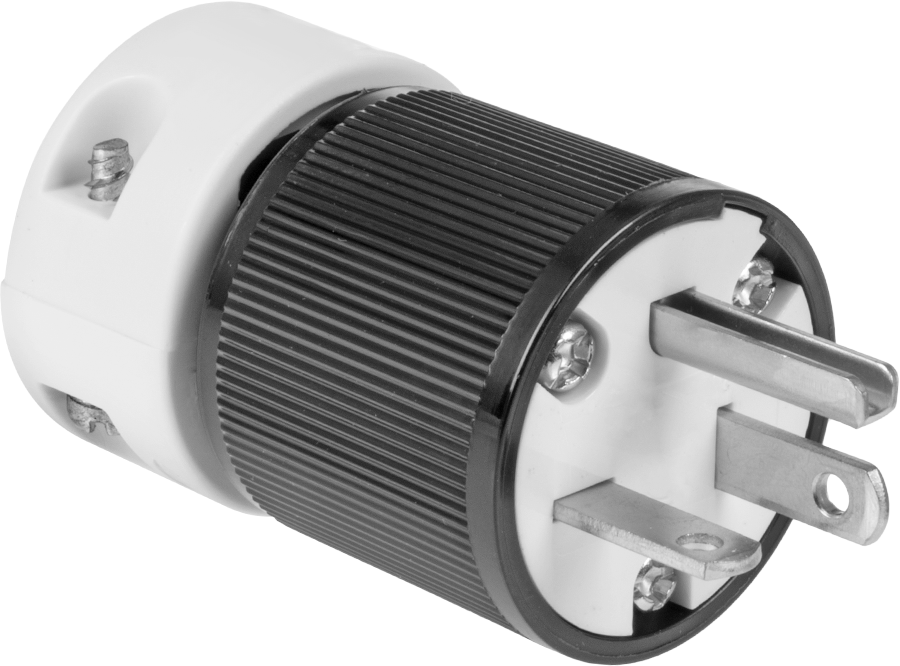
While it's less common you can have dedicated 20A circuit in a home. A 20A circuit would have #12AWG or even #10AWG wire from the panel to the outlet and the outlet SHOULD be a NEMA 5-20R (shown above). Notice the little extra opening on the left side (neutral leg). That helps identify a dedicated 20A receptacle. It's designed to allow a device with a NEMA 5-20P plug that requires 20A to operate and anything with that plug can't be inserted into a 15A receptacle. Many commercial buildings will have 20A circuits. A studio, if properly setup should have all 20A circuits for the 120V service.
Note that just because you see a 20A receptacle doesn't mean it's a true 20A circuit. It could be using #14AWG wire and and 15A circuit breaker at the panel. But typically if they are paying for a 20A receptacle it would be for a true 20A circuit.
Applying this knowledge on set:
So now you know some of the basics to identify/calculate loads and understand some of the limitations of the outlets and wiring you will encounter. How does this can translate to usage on set?
You can't always rely on wattage listed in the name/description for a device as that can be a marketing term that doesn't apply to the device's actual power consumption just it's output.
Remember this: Power output ≠ Power consumption.
As I mention before, nearly all devices will have a power rating plate or sticker. Typically this includes the manufacturer's information, serial number, model number and data about the device's power needs or consumption. They can vary in appearance but can be similar to the one below.
.jpg)
Now for a few other scenarios and devices you might commonly encounter on set.
- An Arri M18 ballast is rated at 20-25A (for 110-120V). Therefore, at full power it's not actually safe to run on a standard 15A outlet in a home. However, if the variator is dialed down on the ballast the power draw is lower. While, it is possible to run a M18 on a standard home outlet below full power output it will often will trip the breaker. If this is happening, things are working as they are designed to prevent a fire. Despite there being a circuit breaker at the panel you could still have a dangerous situation if the receptacle being used isn't wired tightly. Loose connections cause increased resistance and as mentioned before more resistance = more heat which can lead to a burnt receptacle or a fire. It always best to play it safe. It's better to use auxiliary power from generator that can provide a proper 20A circuit to the fixture. If you've ever felt a plug or cable that's warm it's often due to the fact it's running at or near it's limit or there's a loose connection.
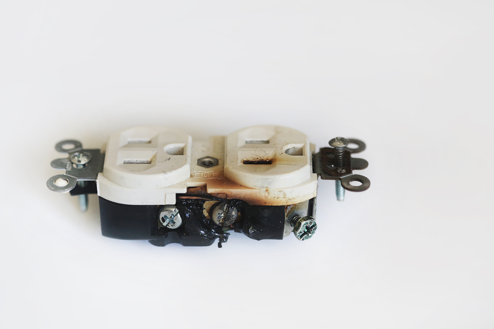 |
| Burnt receptacle from a loose connection. |
You should be aware that typically an HMI's power draw can be ~10-20% or more higher than the rated output for the lamp. For example, a Joker Bug 800W's ballast is rated at 900W/7.5A. And, as mentioned before an Arri M18's ballast is rated at 20A-25A/2400W-3000W at full output for an 1800W fixture.
- An Aputure 600's power supply is rated at 8A at full power. While it outputs a great amount of light for consuming 8A you still need be aware that running two of them at full power on a single 15A circuit is not advised as it will be a total of 16A. On a 15A circuit with a single Aputure 600 at full power you'd still have 7A available for other devices like a monitor, computer or other light source. Just use what you've learned to total up the Amps or Watts to double check it's within the 15A/1800W limit.
- A Profoto Pro 11 pack is rated at 20A. Despite that rating it's typically fine on 15A circuit because that 20A isn't at 100% duty cycle, it's in bursts. When doing high speed shooting and faster recharge it can draw more and will be prone to tripping the circuit breaker. These spikes can be as much as 30A from what I understand. (I've never got around to testing myself with an ammeter)
- In a studio you often see a 100Amp "lunch box" distribution (or distro) similar to the one below. It will have 5x 20A duplex receptacles. So that's 5 separate 20A circuits totaling 100A. There's various styles and sizes of distro boxes but the 100A box is the most common. You will often see green dots on the receptacles, this indicates each one has a dedicated ground and that is connected all the way back to the panel/source. These distro boxes are fed via "Bates" cable that is typically rated for 100A or 60A depending on it's usage. These consist of #4AWG wire for the Hot and Neutral and #6AWG for the ground. These cables get their name from the paddle connectors on them.
.jpg) |
| 100Amp "Lunch Box" distro box |
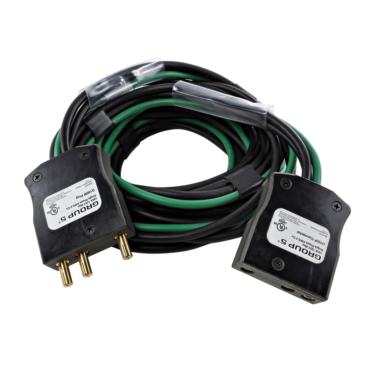 |
| 50ft 100Amp "Bates" cable. |
Without going into all the various ways and sources that power can be provided in studio or on location and the complexities each bring, knowing the basics explained above will help you identify and manage 120VAC on set. Always read the power rating label to understand the max draw of the devices you plan on using on set and and use that information to determine a plan for powering everything on set.
I think it's worth owning a Kill-A-Watt device to check things around your home to get an idea of the consumption of various devices to help build a knowledge of different demands of devices and compare against their listed power ratings.
With this base of knowledge you should be more confident in dealing with and understanding basic power distribution on set.
A few things to keep in mind:
- Outside of a professional studio or professional power distro on a production, assume that every outlet you encounter is only rated for 15A/1800W.
- Assume that every outlet and the overhead fixtures in a room are on the same circuit. So, at a bare minimum when trying to split up packs/fixtures, running one pack/fixture per room is a good rule of thumb.
- You never really know the wiring layout for a structure. Looking at the circuit panel can help provide some information to educate you but that's only if it is properly labeled in the first place.
- Never use damaged cables or cables with loose plugs. Never use a loose receptacle.
With this general knowledge of basic elements you can tackle some basic tasks with a little more confidence. In part two I will cover splicing cables, replacing plugs and some simple tools that might be worth owing or keeping in your kit.
If you would like to support the efforts of the blog you can donate here or here.


